Lights on - lights off
Sunday 21 March 2021
3D
Now that the outline of the name sign is clear, it’s time to look at the next topic: how to add light to it? I want to be able to control the color of the LEDs, I will need to investigate how to do that. And I need to figure out how to make sure that the front of the characters diffuses the light so that the individual LEDs are not showing.
A quick search on the Internet showed that LED strips differ by the amount of LEDs per meter. This means that I also need to figure out which one to buy. Since I have no clue how much light these strips produce, nor how much light will be lost by the front of the characters, I will probably have to experiment a bit to find the answers.
LEDs
I couldn’t figure out how much light these LED strips produce. Sure, there’s information out there that states what such a strip does, but it only gives me a number that I can’t relate to. The easy way would be to buy a strip with the highest number of LEDs per meter. But then I found the power consumption of such a strip and looking at the size of the name sign, I may end up with a small heater…
While searching for LED strips, I found a small LED matrix with 8 by 8 LEDs.
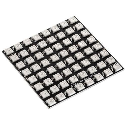
The size of the matrix is 65 x 65 mm. That’s roughly 7mm between the center of each LED, which is almost 140 LEDs per meter. The highest density LED strip that I found has 144 LEDs per meter. So, by using this matrix, I should be able to see how much light such a strip can produce. And by not using all LEDs of the matrix, I can get close to a 60 LED per meter strip as well. The matrix uses WS2812B LEDs; that type is also used by most LED strips. So, let’s order one to experiment with.
How to control the LEDs?
You can’t just apply power to these LEDs to turn them on or off. A WS2812B LED is a combination of 3 color LEDs and a WS2811 controller chip to control each of these LEDs. All of that is packaged in a housing of 5 x 5 mm. Each WS2812B LED has a power and ground connection and a data-in and data-out connection. To control the color and intensity of the LED, the data-in needs to have a certain format and the WS2811 controller will make sure that the correct color is represented. You can connect multiple WS2812B LEDs to each other, by connecting the data-out and data-in pins of the individual LEDs. The first LED in the chain will need to be connected to a computer or microcontroller. That’s the theoretical story.
To use the LED matrix, I need a computer or microcontroller. Looking at my name sign, adding a Raspberry Pi to only control the LEDs is overkill. Next to that, a computer with a full fletched operating system is not the best way to control the LEDs. Timing of the data stream from the computer to the LEDs is critical and with that in mind, a microcontroller is a better choice.
The world of microcontrollers
The last time I used a microcontroller was back in 1990 (give or take a few years) and I can’t imagine that technology has not changed since then… Anyone that ever used a Raspberry Pi, probably has stumbled upon the Arduino boards. The Arduino boards are based on a particular microcontroller and are a great way to learn how to use a microcontroller. But there are far more options out there. A bit of research brought me to the ESP8266.
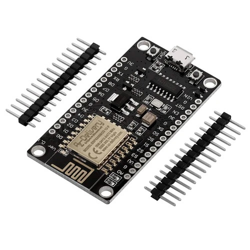
These things pack an incredible number of features and functionality in a small chip/board. They come with Wi-Fi, which allows me to interact with the device over the network (one of my requirements). And they are far less expensive than the Arduino boards. It’s just amazing to see what happened over the last 30 years. Another item for my order. There’s one small detail that I need to take care of as well: the LEDs work at 5V, but the ESP8266 is operating at 3.3V. This is where the TXS0108E comes into the picture.
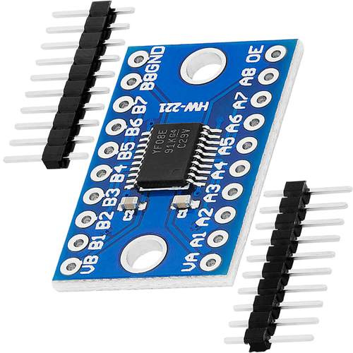
The TXS0108E is an 8-bit bi-directional level shifter or voltage translator. This chip has 2 sides; one is connected to 3.3V and the other one to 5V. It can then translate the signal from one side to the other and this allows you to connect a 5V device to a 3.3V device.
Let’s connect the wires
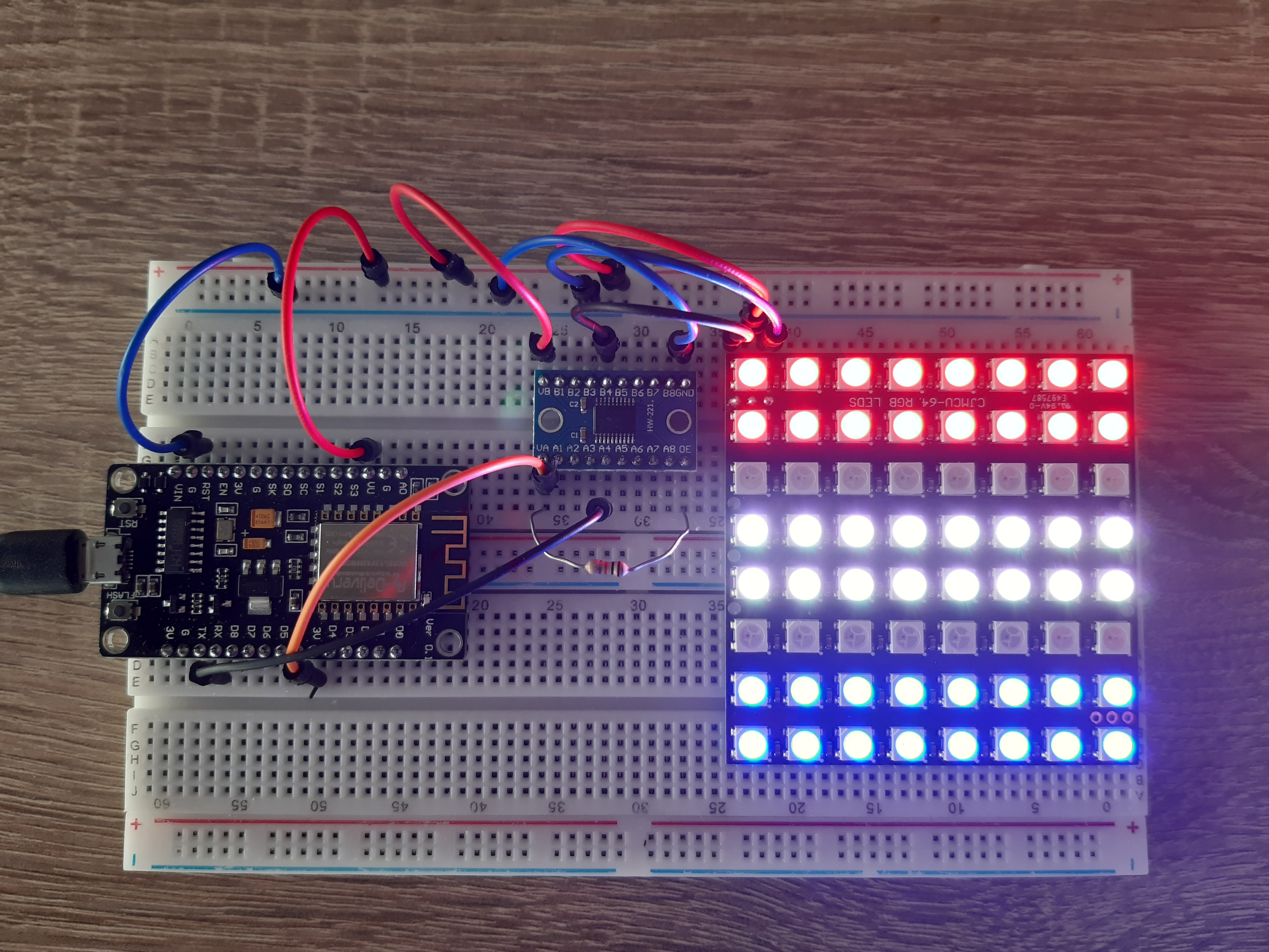
I ordered all the kit and after a few days it was time to unpack boxes and stick all components on a breadboard. Hardware: done.
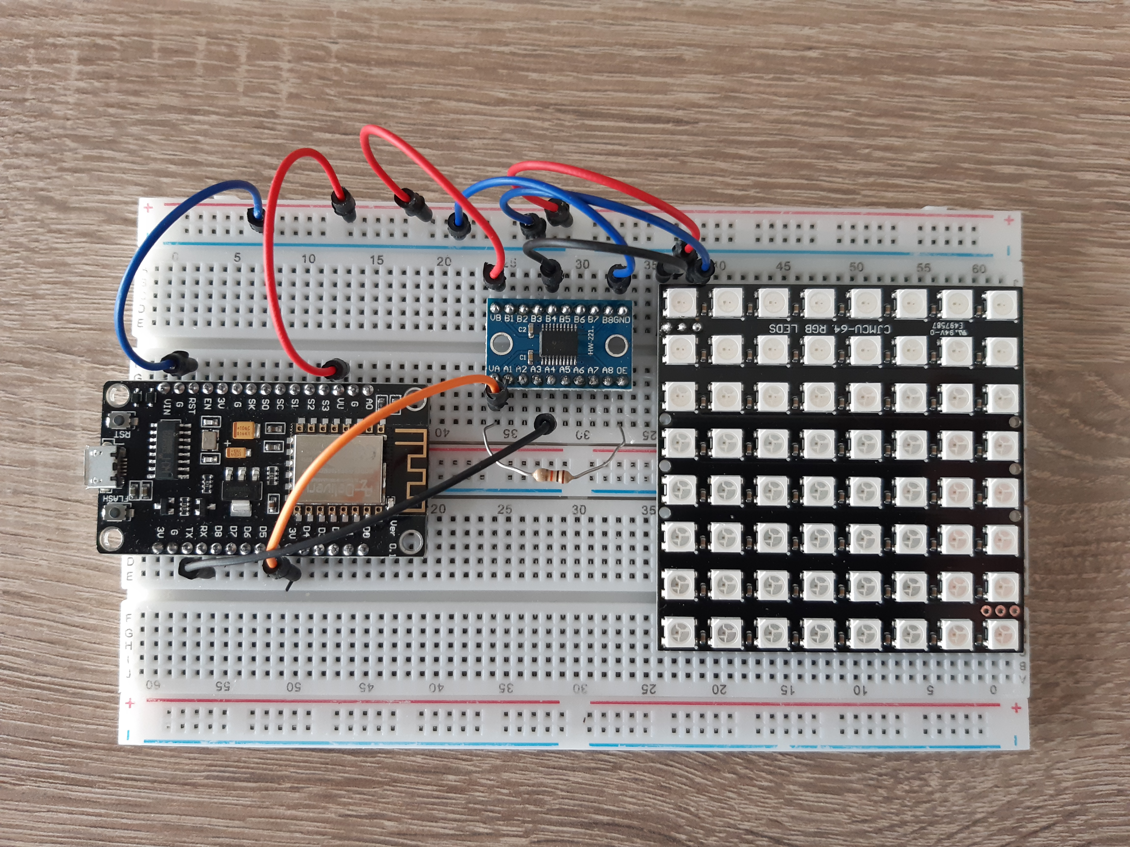
Looks great but doesn’t do anything unless we add some software to it.
Time to download and install the Arduino IDE and the driver for the CH340/CH341 USB-Serial chip installed on the microcontroller board. Once that was done, it was time to add the ESP8266 to the Arduino IDE. Job done; let’s build some software.
To make sure that basic stuff was working, I started out by compiling and flashing some of the examples that came with the ESP8266 package. This allowed me to find my way around in the IDE and see how to use the serial port of the controller to share information with the computer while debugging.
Then it was time to see how to get the LED matrix working. There are a few libraries out there that can be used to interact with WS2812B LEDs. After some research, I concluded that NeoPixelBus would make the most sense. NeoPixelBus not only supports LED strips where the LEDs are in one long string, but it also supports LED matrix panels. I used one of the examples; put in the dimensions and LED orientation of my panel and flashed it to the microcontroller. After a few attempts, I got the layout correct and things worked like they should.
Then it was time for the next step: connect to the network. Again, I found some examples in the ESP8266 package and was able to connect to my Wi-Fi access point. Then I tried an example that turns the microcontroller into a small webserver. Got that up and running in no time as well.
Experimenting with the LEDs
Time to focus on the actual questions: how much light do these LEDs generate and how does that impact the design of the name sign?
I realized that I need a fast way to switch individual LEDs on and off and be able to control the color and intensity of them to see the impact of settings. To do so, I searched for some ideas and came across an example that turned the microcontroller into a webserver and serve a web page that interacts with the webserver to switch LEDs on or off. That project was very limited in functionality; it only allows turning LEDs on and off, but it got me thinking about what I wanted and how to do that.
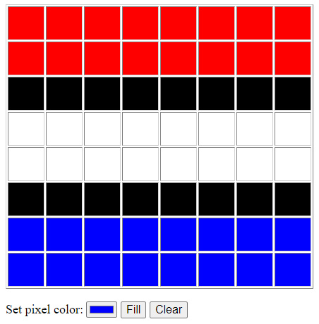
After a few days of tinkering with the code, I got a working solution. Once the microcontroller starts, it connects to the network. Using a browser, brings up a page as shown in the picture below. By ticking the individual boxes, you can turn the LEDs on or off and set the color.
This is the source of the code used for the microcontroller:
#include <ESP8266WiFi.h>
#include <WiFiClient.h>
#include <ESP8266WebServer.h>
#include <ESP8266mDNS.h>

// We use this library to control the LED matrix
//  https://github.com/Makuna/NeoPixelBus
#include <NeoPixelBus.h>

// The index_html.h file contains the client side web page.
#include "index_html.h"

// Never include the WiFi settings in the code...
// The wifi_setting.h file defines the ssi and password.
#include "wifi_settings.h"

// Define the dimensions of the LED matrix.
const uint8_t PanelWidth  = 8;
const uint8_t PanelHeight = 8;
const uint16_t PixelCount = PanelWidth * PanelHeight;

// Define the layout and config of the LED matrix.
NeoTopology<RowMajorLayout> topo(PanelWidth, PanelHeight);
NeoPixelBus<NeoGrbFeature, Neo800KbpsMethod> leds(PixelCount);

// Define the webserver.
ESP8266WebServer server(80);

// Some support functions to handle the onboard LED
void ledOn() {
  digitalWrite(LED_BUILTIN, LOW);
}
void ledOff() {
  digitalWrite(LED_BUILTIN, HIGH);
}
void ledToggle() {
  digitalWrite(LED_BUILTIN, !digitalRead(LED_BUILTIN));
}
esp8266::polledTimeout::periodicFastUs ledBlinkingPeriod(500000);

// Here we go.
void setup() {
  Serial.begin(115200);
  while (!Serial); // wait for serial attach

  Serial.println();
  Serial.println("Initializing...");

  // This is the onboard LED that we use to
  //  indicate what the controller is doing.
  pinMode(LED_BUILTIN, OUTPUT);

  // Configure the WiFi settings.
  WiFi.mode(WIFI_STA);
  WiFi.begin(WIFISSID, WIFIPWD);
  Serial.print("Trying to connect to: ");
  Serial.println(WIFISSID);

  // Try to connect to the WiFi network.
  // The onboard LED is used to identify that
  //  we are trying to connect to the network.
  while (WiFi.status() != WL_CONNECTED) {
    delay(400);
    ledOff();
    delay(100);
    ledOn();
    Serial.print(".");
  }

  // By now, we are connected to the network.
  // The blinking frequency of the onboard LED
  //  now indicates "normal operation".
  ledOff();
  ledBlinkingPeriod.reset();

  Serial.println("");
  Serial.print("Connected to: ");
  Serial.println(WiFi.SSID());
  Serial.print("Signal strenght: ");
  Serial.println(WiFi.RSSI());
  Serial.print("IP address: ");
  Serial.println(WiFi.localIP());

  // Set server callback functions
  server.on("/",          on_homepage);
  server.on("/config.js", on_config);
  server.on("/cc",        on_change_color);
  server.begin();
  Serial.println("HTTP server started");

  // Initialize the LED matrix
  leds.Begin();
  leds.Show();

  // After programming the controller, some LEDs may be on.
  // With this step, we make sure that they are all off.
  // The library may think that nothing changed after the ClearTo()
  //  call, that's why we flag it Dirty() here to force an update.
  leds.ClearTo(RgbColor(0,0,0));
  leds.Dirty();
  leds.Show();
}

void loop() {
  // The onboard LED blinks at a low frequency
  //  to indicate that the controller is still alive.
  if (ledBlinkingPeriod) {
    ledToggle();
  }

  // Check if there is a web browser requesting something.
  server.handleClient();
}

// A new connection from a web browser.
// Upload the /index.html file to the browser.
void on_homepage() {
  Serial.println("on_homepage()");

  String content = FPSTR(index_html);
  server.send(200, "text/html", content);
}

// The index.html file does not contain the setup
//  of the LED matrix. For that we use a seperate
//  javascript file. The browser is requesting
//  that file now.
void on_config() {
  Serial.println("on_config()");

  String content = "";

  content += "const PanelWidth  = " + String(PanelWidth) + ";\n";
  content += "const PanelHeight = " + String(PanelHeight) + ";\n";
  content += "const PixelCount  = PanelWidth * PanelHeight;\n";
  content += "const Path = '/cc?pixels=';\n";

  server.send(200, "text/javascript", content);
}

// The web browser would like to update the LED matrix.
void on_change_color() {
  Serial.println("on_change_color()");

  uint16_t i;
  HtmlColor color;

  if(server.hasArg("pixels")) {
    String val = server.arg("pixels");
    Serial.print("-> with pixels; value = ");
    Serial.println(val);

    for(i=0; i<PixelCount; i++) {
      String color_string = String("#") + val.substring(i*6, i*6+6);
      uint8_t result = color.Parse<HtmlColorNames>(color_string);
      leds.SetPixelColor(i, color);
    }

    leds.Show();
  }

  server.send(200, "text/html", "{\"result\":1}");
}
This is the web page as served by the microcontroller. It is stored as a string in the code and uploaded when a web browser requests it.
const char index_html[] PROGMEM = R"(
<head>
    <title>WiFi Matrix Control</title>
    <meta name='viewport' content='width=device-width, initial-scale=1'>
    <style>
        .color-sel {
            width: 24px;
            height: 24px;
            text-align: center;
        }

        .pixel-sel {
            width: 48px;
            height: 48px;
            background-color: black;
        }

        button {
            font-size: 16px;
        }

        p {
            font-size: 18px;
            font-style: normal;
            line-height: 0px;
        }

        table {
            border-color: lightgray;
            border-collapse: collapse;
        }
    </style>
</head>

<body>
    <script src="/config.js"></script>

    <script>
        const Black = 'rgb(0,0,0)';

        function w(s) { document.write(s); }

        function id(s) { return document.getElementById(s); }

        function hex2rgb(h) {
            r = parseInt(h.substr(1, 2), 16);
            g = parseInt(h.substr(3, 2), 16);
            b = parseInt(h.substr(5), 16);

            return 'rgb(' + r.toString() + ', ' + g.toString() + ', ' + b.toString() + ')';
        }

        function rgb2hex(rgb) {
            if (!rgb) return '000000';
            rgb = rgb.match(/^rgba?\((\d+),\s*(\d+),\s*(\d+)(?:,\s*(\d+))?\)$/);
            function hex(x) { return ('0' + parseInt(x).toString(16)).slice(-2); }
            return '' + hex(rgb[1]) + hex(rgb[2]) + hex(rgb[3]);
        }

        function ps_click(e) {
            if (e.target.style.background == CurrentColor())
                e.target.style.background = Black;
            else
                e.target.style.background = CurrentColor();

            send();
        }

        w('<table border=1 style="border-collapse: separate; border-spacing: 2px;">');
        idx = 0;
        for (i = 0; i < PanelHeight; i++) {
            w('<tr>');
            for (j = 0; j < PanelWidth; j++, idx++) {
                w('<td class=pixel-sel id=ps' + idx + '></td>');
                id('ps' + idx).addEventListener('click', ps_click);
            }
            w('</tr>');
        }
        w('</table>');
    </script>

    <p>
        Set pixel color:
        <input type='color' id='btn_color' value='#880000'>
        <button id='btn_fill'>Fill</button>
        <button id='btn_clear'>Clear</button>
    </p>

    <script>
        id('btn_fill').addEventListener('click', function (e) {
            for (i = 0; i < PixelCount; i++) id('ps' + i).style.background = CurrentColor();
            send();
        });

        id('btn_clear').addEventListener('click', function (e) {
            for (i = 0; i < PixelCount; i++) id('ps' + i).style.background = Black;
            send();
        });

        function CurrentColor() {
            h = id('btn_color').value;
            return hex2rgb(h);
        }

        function send() {
            var fullmatrix = Path;
            for (i = 0; i < PixelCount; i++) fullmatrix += rgb2hex(id('ps' + i).style.background);

            var xhr = new XMLHttpRequest();
            xhr.onreadystatechange = function () {
                if (xhr.readyState == 4 && xhr.status == 200) {
                    var jd = JSON.parse(xhr.responseText);
                }
            };
            xhr.open('GET', fullmatrix, true);
            xhr.send();
        }
    </script>
</body>
)";
At this point, I have a nice way to experiment with the LEDs. The next step is to figure out how to print a light diffuser and find out which LED strip to buy for the name sign. More on that in another post.
Want to respond to this post?
Look me up on GitHub,
 Facebook or
 LinkedIn.
Tags
- 3D 9
- Air Safari 19
- Australia 67
- BlackBerry 1
- Blue Sky Flying Adventures 33
- By Boat 4
- By Bus 2
- Dev Containers 3
- Domoticz 2
- Driving 31
- Facebook 1
- Flying 44
- Gallery 2 7
- Google Maps 4
- Hugo 1
- Jekyll 4
- Linux 3
- NextGEN Gallery 5
- Owning a plane 8
- Podman 3
- Red Centre Tour 19
- Singapore 3
- Tasmania 10
- USA 33
- WSL 2 4
- Walking 42
- WordPress 17